Packing friction plays an important role in the sealing of pumps and valves. Ideally, sealing is accomplished with the lowest practical frictional drag. Some frictional losses occur when the packing is compressed axially in the stuffing box to produce the radial contact that controls leakage. This radial load must produce a contact pressure on the shaft or stem and bore high enough to overcome the process fluid pressure. The equipment shaft, spindle or stem drive mechanism has to readily overcome static and dynamic or running friction during operation.
High packing friction can impede the equipment performance and efficiency by generating too much drag and heat. Excessive drag increases equipment power consumption and operating cost, and can ultimately result in equipment failure.
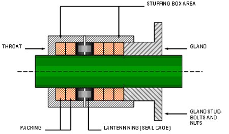
Figure 1. Typical stuffing box arrangements
Friction Definitions
Static friction occurs when there is no relative motion between the packing and the mating surfaces including the shaft or stem. This type of friction is prevalent in manual valves. With no relative motion, this higher frictional force must be overcome when motion is attempted.
Dynamic or running friction occurs during relative motion between the packing and the shaft, spindle or stem. This frictional force has to be overcome by these rotating or reciprocating elements.
Material
The coefficient of friction varies between packing materials. Some inherently possess a low coefficient because of the nature of the raw material. Graphite is one example of a material with inherent low friction characteristics. In general, PTFE has the lowest friction coefficient, with graphite not far behind. At temperatures less than 500-deg F, PTFE packing exhibits the lowest friction coefficient. The drawback is that it does not dissipate heat as effectively as flexible graphite. Flexible graphite and graphite yarn produce low coefficients of static and dynamic friction. Flexible graphite exhibits a friction advantage in both low and high-temperature applications. The combination of PTFE and graphite yields the best coefficient of friction: 0.15 to 0.05 for static and dynamic friction, respectively.
In some cases, end rings of braided graphite or carbon yarn packing or wire-reinforced braided packing are used as “wiper rings” to reduce friction by minimizing the build-up of graphite on the moving surfaces. They also work well to inhibit packing extrusion and help to support the radial whip of the rotating or reciprocating shaft/stem.
Number of Rings
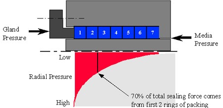
Often, the number of packing rings in the stuffing box far exceeds what is necessary for sealing. Too many rings increase the contact area on the shaft/stem in excess of what is needed for effective sealing. As a result, the packing drag prohibits the shaft/stem from moving effectively, even if it is air- or motor-operated. A large number of rings generally increases the static or breakaway friction as well as the dynamic or running friction. The best practice usually is to use five packing rings and a solid carbon bushing to fill the rest of the stuffing box.
Figure 2. Packing radial pressure distribution
Packing Ring Cross Section
Square cross-section rings are used in the majority of dynamic applications. Cone-shaped moulded packing made of the proper density provides superior radial expansion capability at lower gland pressure, which may be one reason why cone-shaped packing performs with low friction in valves that cycle several thousand times an hour. Due to the narrow cross-section of some stuffing boxes, it may be difficult to design a cone or wedge seal to fit. Furthermore, if one is designed, it may be extremely difficult to install. While both the wedge and cone designs initially give low breakaway friction, studies show that there is little difference in running friction once packing consolidation is achieved. For quick turnaround and availability, square packing rings are more readily available and installation can be accomplished with less difficulty.
Lubrication
Braided packing friction can be reduced by the addition of suitable lubricants in the packing during the manufacturing process. However, these lubricants can be destroyed by excessive tightening of the packing or thermal decomposition from the operating conditions. Also, some chemicals can react with certain lubricants, causing the lubricants to quickly dry out and the packing to become brittle and abrasive to the shaft/stem. Using a clean external flush system will help cool and lubricate pump packing and reduce friction.
If pump packing has lost its lubrication from over-tightening, it is imperative to back out the gland bolt to allow the process fluid to leak around the shaft. This will provide lubrication and cooling between the packing and the shaft.
Conclusion
Excessive packing friction adversely impacts pump and valve performance and energy consumption, which translates to an increase in operating and equipment cost. Excessive packing friction may also increase equipment downtime due to packing failure and/or sudden equipment failure. Packing friction can cause major wear damage to the pump shaft or sleeve. It may also cause overloading of the equipment drive mechanism, which can cause overheating and damage to the pump or valve motors. The demand imposed at start-up by breakaway friction on the packed pump motor, air- or hydraulic-driven shaft/stem can be overwhelming. If the torque to overcome the packing friction exceeds the maximum power of the drive mechanism, it may cause catastrophic failure and may even cause harm to the operator.
To mitigate excessive compression packing friction, consider the following:
- Use the packing material and design that will seal without generating excessive friction.
- Ensure that the equipment is in satisfactory operating condition.
- Employ additional cooling and lubrication by injecting lubricant into pump packing through the lantern ring.
- Allow appropriate leakage of the fluid, at least 60 drops per minute in most pump applications, to provide a film of lubrication between the packing and the shaft.
- Repack the equipment when the packing and gland are fully compressed if leakage is excessive. Do not install additional packing rings.
- To control pump packing leakage, make gland adjustments at 15-minute intervals, tightening one flat at a time.
- After installing pump packing and slightly hand-tightening the gland, start and stop the pump a few times before restarting.
- Ensure that the packing width follows the rule of thumb of shaft/stem diameter to packing width ratio less than or equal to 4 (SD/PW ≤ 4), otherwise, the packing might not seal properly.
For more information on this topic see the following sections in the newly published FSA-ESA Compression Packing Technical Manual: (Copies are available from PUMPNSEAL) How packing works, Valve packing types, Pump packing types, Specialty equipment packing, Advances in compression.


